Final Project
Smart Sole

Smart Sole Logo
Inspiration
As a biomedical engineering concentrator, I'm very interested in fabricating devices with clinical applications. As I wrote in my Week 1 Introduction, I wanted my final project to incorporate wearable technonology. The idea of making a Smart Sole capable of tracking an athlete's form came to me after my roommate injured himself during a morning jog. I had flashbacks to my high school cross country days when my coach would constantly remind us to run with proper form. I decided to create an insertable shoe sole with force sensitive resistors (FSRs) to solve the issue of athletes running with improper form.Design
In my initial design of the Smart Sole, I intended for there to be 8 FSRs layed out throughout the sole with an ESP32 Feather attached to the shoe via an external compartment. Using an ESP32 Feather would allow the Smart Sole to wirelessly communicate with a live database, so the user need not be attached to a computer. Ideally the device would have functioned using Bluetooth (as illustrated in the schematic to the right), but it ended being easier to integrate WiFi.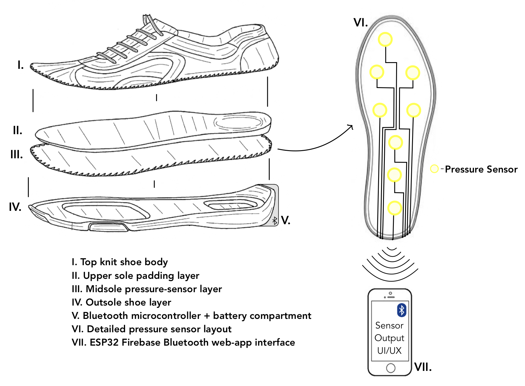
Initial Smart Sole Design
Prototyping
To create the Smart Sole, I first traced and cutout an outline of my foot on paper to use as pattern for the sole's fabric and circuit base. Using this pattern, I cut out the shape in foam board to build an initial circuit. In the prototyping stage I used an Arduino MKZero to experiment with FSR placement on this foam cut-out using voltage dividers as the sensing technique (the Arduino code used to test this prototype is at the bottom of the page). I also traced the pattern onto muslin fabric to cut and sew a sample "glove" for the sole's circuit base.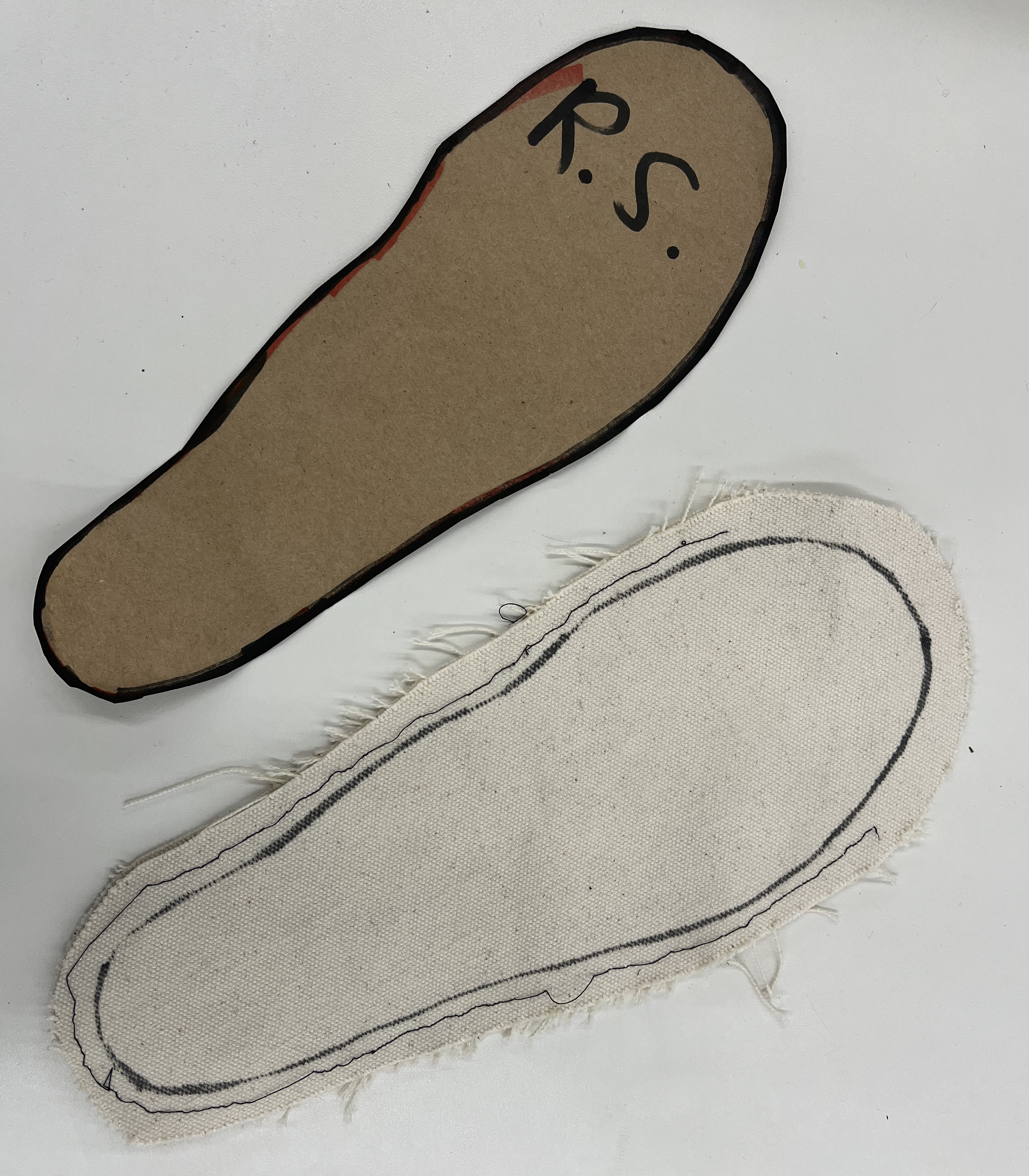
Paper Pattern & Muslin Prototype
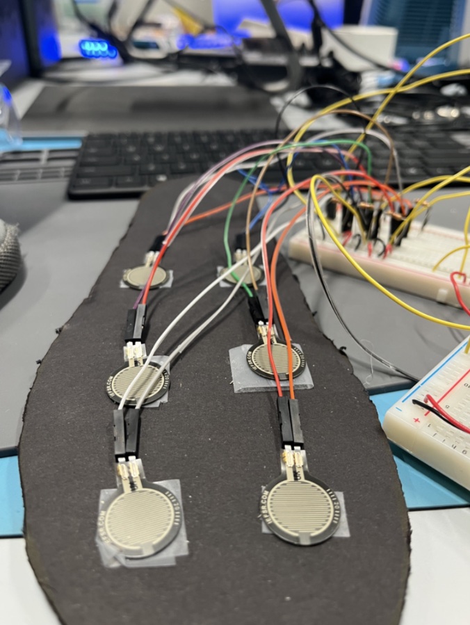
Smart Sole Prototype
Construction
After successfully creating a prototype for the Smart Sole, I moved on to the final circuit build out and fabric cushioning construction. I used a neoprene-like fabric for the final circuit "glove" as it provided enough protection of both the microcontroller and the user's foot. On a new cutout foam board, I soldered the FSRs directly to the ESP32 Feather. The 1 kΩ resistors used in the voltage divider circuits were soldered directly to the FSRs with the signal wires. The signal wires went to pins 33, A2, A4, A3, 32, 14 on the ESP32 Feather. A 3.7 volt rechargable Lithium battery was used to power the wireless device.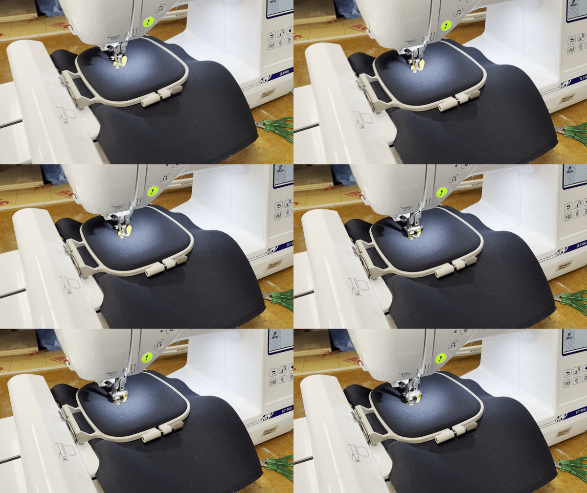
CNC Embroidery Process
Sewing Final Sole Cover
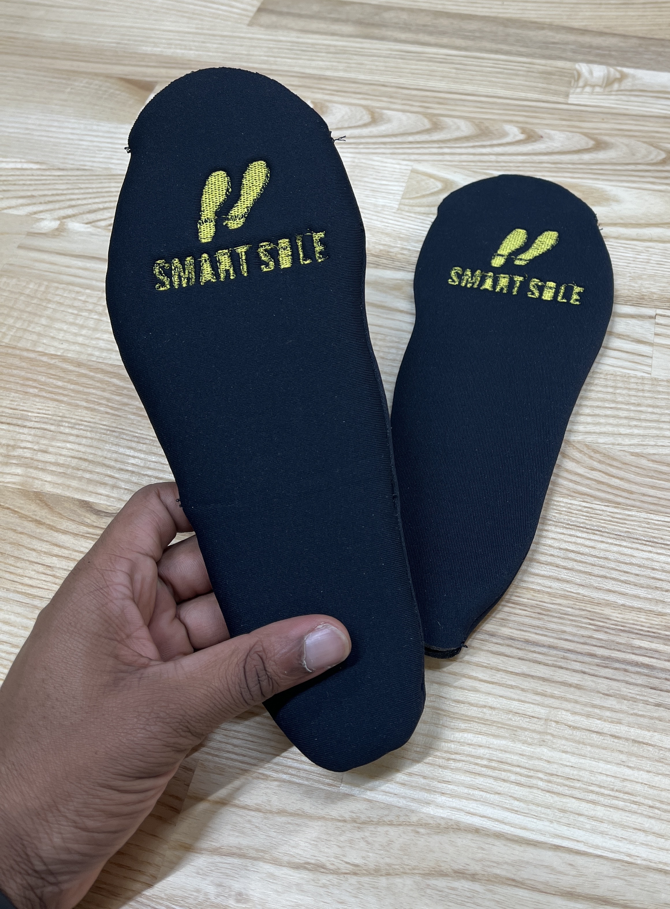
Final Neoprene Sole Cover
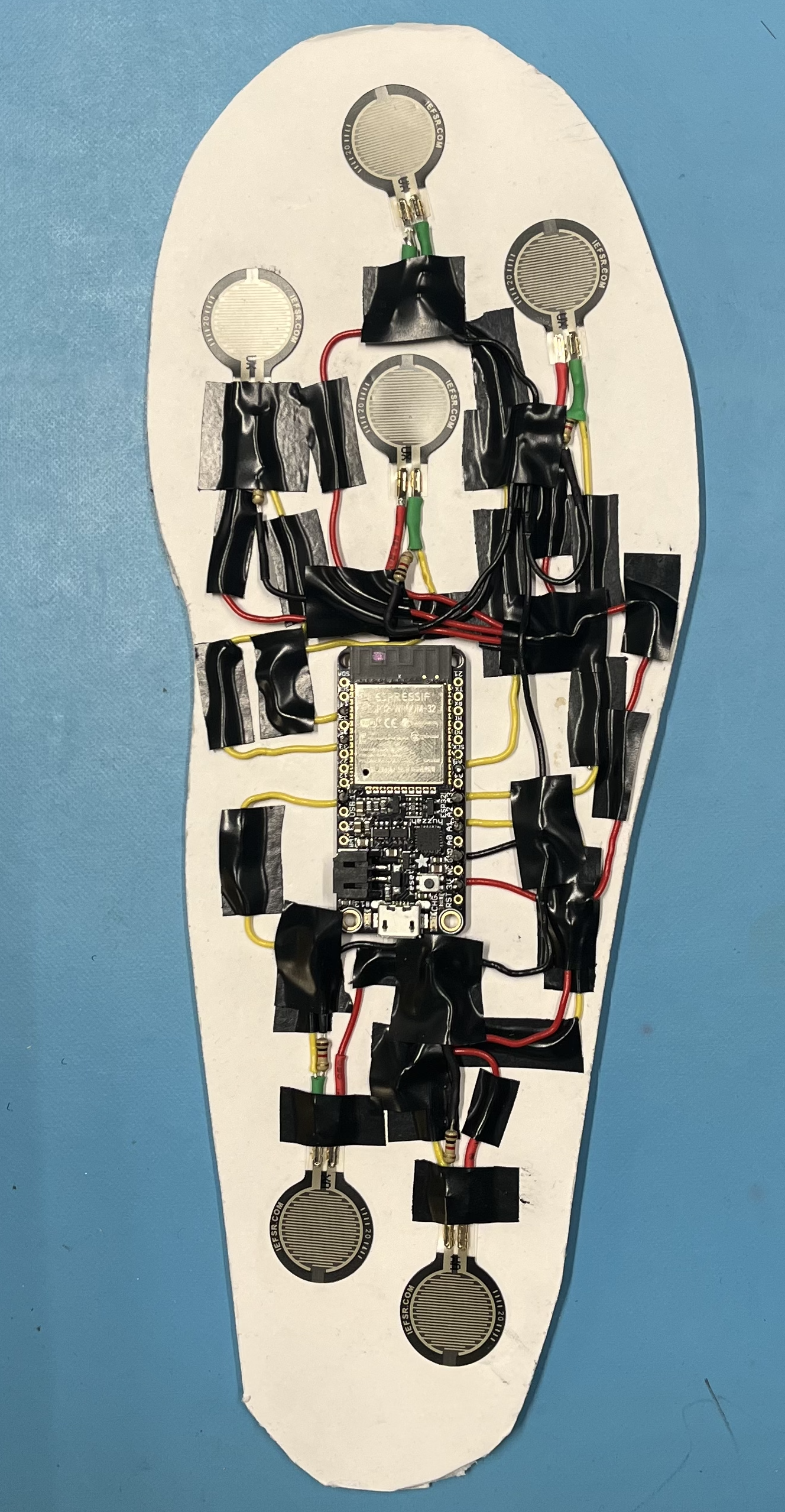
Final Circuit
With the final circuit completed constructed, I connected the ESP32 Feather to the "Harvard University" Wireless Network for testing. An issue I ran into when testing out the final circuit using WiFi communication was that some of the analog pins were not being sent to the live database (Google Firebase). After several hours of troubleshooting, I realized that this was because I had initially connnected some of the FSR signal wires to ADC pins on the ESP32 Feather that did not work with wireless communication. In fact, there are only 5 ADC pins that work wirelessly. I had to resolder 4 of the FSRs and complete eliminate another from the sole's layout to account for this. The diagram below displays a schematic of the final Smart Sole showing the WiFi capable pins.
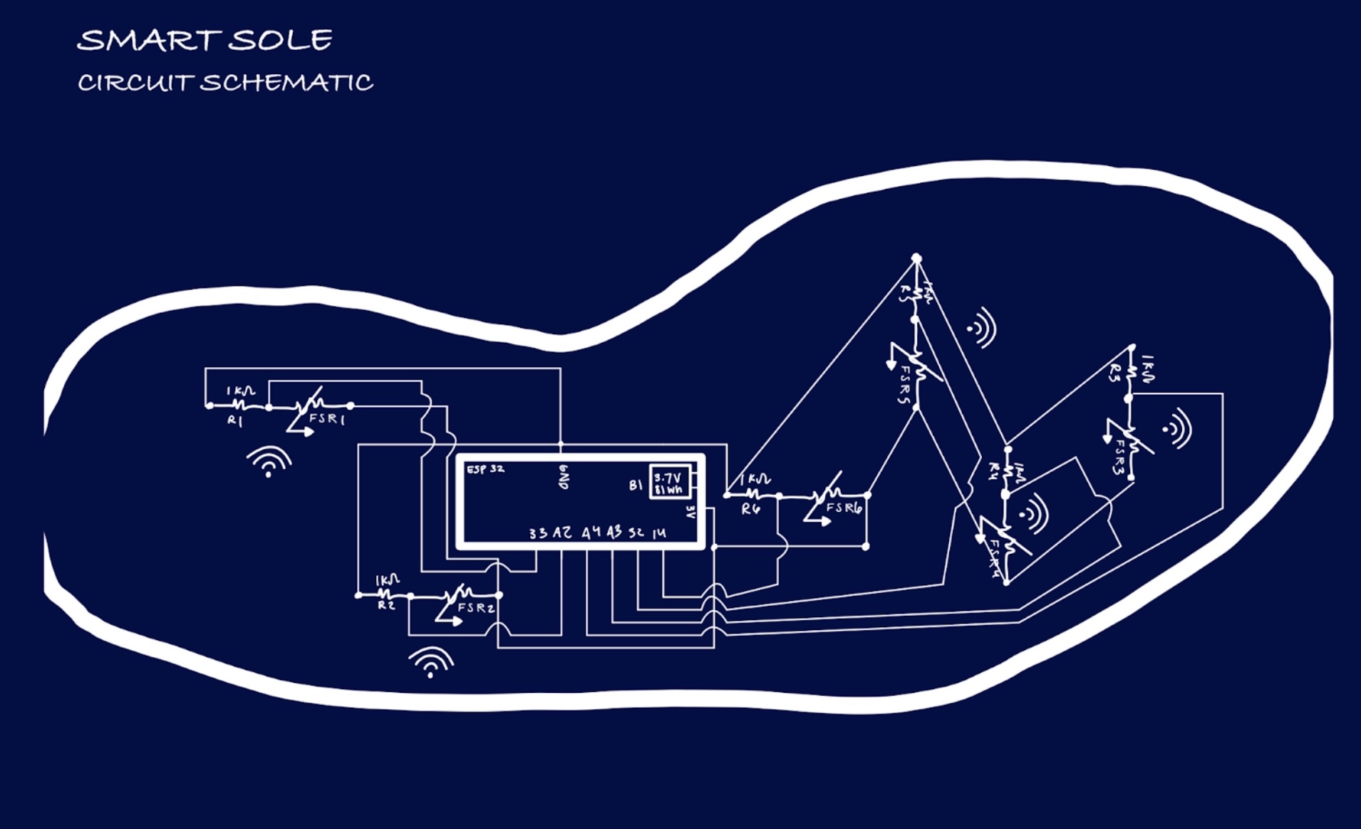
Final Sole Schematic
User Interface
The final sole operated with the user interface shown in Week 11. It features a live updating visualization of the FSR readings with a range of colors indicating the intensity of the foot against the sole. In the real world, an athletic coach might use the Smart Sole to track an athlete's running form during a workout to make subsequent suggestions. For example, if the back two FSRs have more activity than the front three, the coach would be able to tell that the athlete is striking the ground with their heel. Since a ball strike is more ideal, the coach could then give instructions for improving upon this.Materials
- Elmer's® 1/2" Foam Board, 20" x 30"
- Field's Fabrics Neoprene 1-Way Stretch Micro-Foam-Center Fabric
- DMC 117-726 Six Strand Embroidery Cotton Floss
- FSR UX 402 Short (6)
- Adafruit HUZZAH32 – ESP32 Feather Board
- 1 kΩ Resistors (6)
- Hook-up Wire
