
Week 6
Electronic Input Devices
Capacitive Sensor
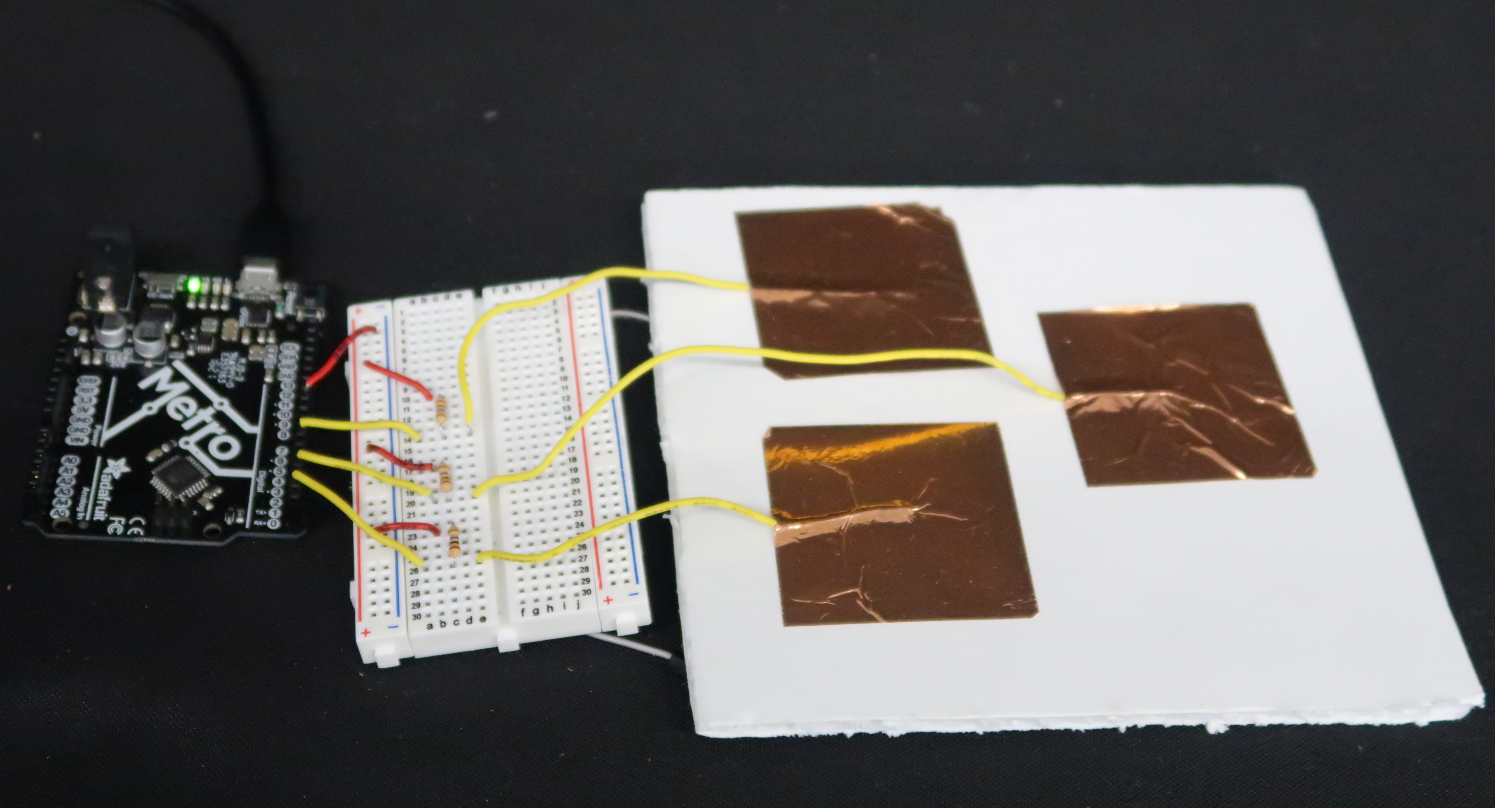
For the first part of this week's assignment, I created three capacitive sensors using copper. The array of capacitive sensors is shown at the top of this page. This Arduino Playground tutorial helped guide the setup of my sensors and how they interfaced with the Arduino Uno. They were essentially connected to the microcontroller via voltage dividers using 1 kΩ resistors. The serial plotter was a bit finnicky, but I was able to calibrate the copper sensors to an extent by varying the pressure of my fingers during the calibration shown in the figure below.
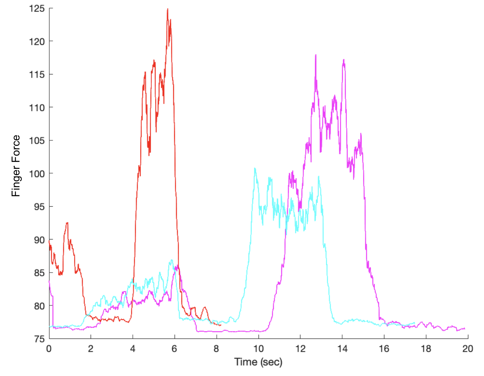
In the figure above, the pink, blue, and red traces correspond to the left, middle, and right copper capacitive sensors respectively. During the calibration, I pressed each of three capacitive sensors with minimal force first and then again with heavier force. The middle sensor (blue) appeared to be the least sensitive to my touch, though all three sensors functioned fairly well. The Arduino Code I used to program the microcontroller for the capacitive sensor is shown below.
Capacitive Sensor Arduino Code:
          #include
          CapacitiveSensor   cs_10_2 = CapacitiveSensor(10,2);
          CapacitiveSensor   cs_10_4 = CapacitiveSensor(10,4);
          CapacitiveSensor   cs_10_7 = CapacitiveSensor(10,7);

          void setup() {
            {
           //  cs_10_7.set_CS_AutocaL_Millis(0xFFFFFFFF);     // turn off autocalibrate on channel 1 - just as an example
             Serial.begin(9600);
          }


          }

          void loop() {
            {
              long start = millis();
              long total1 =  cs_10_2.capacitiveSensor(30);
              long total2 =  cs_10_4.capacitiveSensor(30);
              long total3 =  cs_10_7.capacitiveSensor(30);

              Serial.print(millis() - start);        // check on performance in milliseconds
              Serial.print("\t");                    // tab character for debug windown spacing

              Serial.print(total1);                  // print sensor output 1
              Serial.println(total1);
              Serial.print("\t");
              Serial.print(total2);                  // print sensor output 2
              Serial.println(total2);
              Serial.print("\t");
              Serial.print(total3);                // print sensor output 3
              Serial.println(total3);
              Serial.print("\n");
              delay(10);                             // arbitrary delay to limit data to serial port
          }

          }
Force Sensitive Resistors (FSRs)
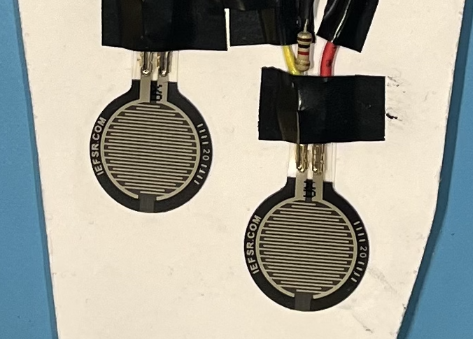
The next sensors that I worked with were FSR UX 402s. I will likely use them in my final project as a way to measure gait. They were very simple to work with and calibrate, as I only needed to create a voltage divider in a breadboard—again with 1 kΩ resistors—and send a signal wire to an analog pin in the microcontroller.
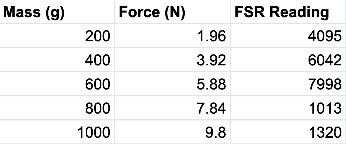
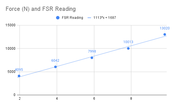
I used weights of increasing mass to calibrate the amount of force that the FSRs were under. The table and graph below show a clean linear relationship (the equation is displayed on the plot) between the force (N) applied to an FSR and the output via the Arduino Serial Monitor. The simple Arduino Code I used to calibrate the FSRs is at the bottom of the page.
FSR Arduino Code:
          void setup() {
            pinMode(A6, INPUT);
            Serial.begin(9600);
          }

          void loop() {
            int pressure = analogRead(A6);
            Serial.print(pressure);
            Serial.print("\n");
            Serial.println(pressure);
            delay(1000);
          }